FXS Blades
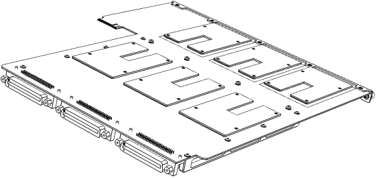
The FXS blade (referred to as Module in the device's management interfaces) provides the FXS port interfaces. Each blade provides three FXS port connectors - 50-pin Telco connector (Centronics type). Each connector provides 24 FXS interfaces and therefore, each blade provides up to 72 FXS interfaces (3 x 24 FXS). The device can be housed with up to four FXS blades thereby, supporting up to 288 FXS port interfaces (4 blades x 72 FXS). The FXS blades are available as spare parts. For replacing FXS blades, see Replacing the Fan Tray Module.
Each FXS blade provides a LED on the front and rear panel, as described in FXS LEDs.
FXS Blade Showing Three FXS Telco Connectors
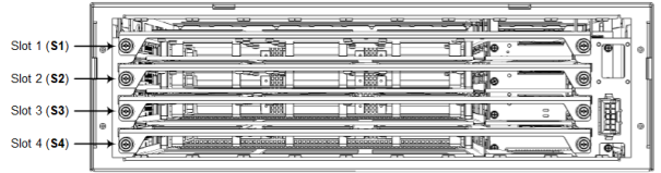
The chassis slot assignment for the FXS blades is shown in the following figure (front panel). Note that the slot labels (S1, S2, S3 and S4) are located on the rear panel.
Chassis Slot Assignment for FXS Blades (Front Panel)
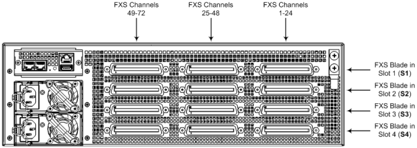
The FXS channel (port) number range of each FXS connector on an FXS blade is indicated by the labels (FXS 1-24, FXS 25-48, and FXS 49-72) located on the rear panel above the FXS blades, as shown in the following figure:
FXS Blades and FXS Channels per FXS Connector (Rear Panel)
The following table lists the specifications of the device's FXS ports.
FXS Port Specifications
|
Specification |
Description |
||||||||||||
|---|---|---|---|---|---|---|---|---|---|---|---|---|---|
|
Analog Lifeline (PSTN Fallback) |
The FXS blade supports analog lifeline (PSTN Fallback). For more information, see Connecting the FXS Analog Lifeline. |
||||||||||||
|
Interface Type |
FXS connection via 50-pin CHAMP connector |
||||||||||||
|
FXS Signaling Formats |
In-band signaling DTMF (TIA 464B) |
||||||||||||
|
FXS Loop Impedance |
Up to 1500 ohm (including phone impedance) |
||||||||||||
|
Off-hook Loop Current |
|
||||||||||||
|
Ring Voltage (Sine) |
Note:
|
||||||||||||
|
Ring Frequency |
25-100 Hz |
||||||||||||
|
Maximum Ringer Load |
Ringer Equivalency Number (REN) 3 |
||||||||||||
|
Caller ID |
Bellcore GR-30-CORE Type 1 using Bell 202 FSK modulation, ETSI Type 1, NTT, Denmark, India, Brazil, British and DTMF ETSI CID (ETS 300-659-1) |
||||||||||||
|
Polarity Reversal / Wink |
Immediate or smooth to prevent erroneous ringing |
||||||||||||
|
Metering Tones |
12/16 KHz sinusoidal bursts; generation on FXS |
||||||||||||
|
Distinctive Ringing |
By frequency (15-100 Hz) and cadence patterns |
||||||||||||
|
Message Waiting Indication (MWI) |
DC voltage generation (TIA/EIA-464-B); V23 FSK data; Stutter dial tone |